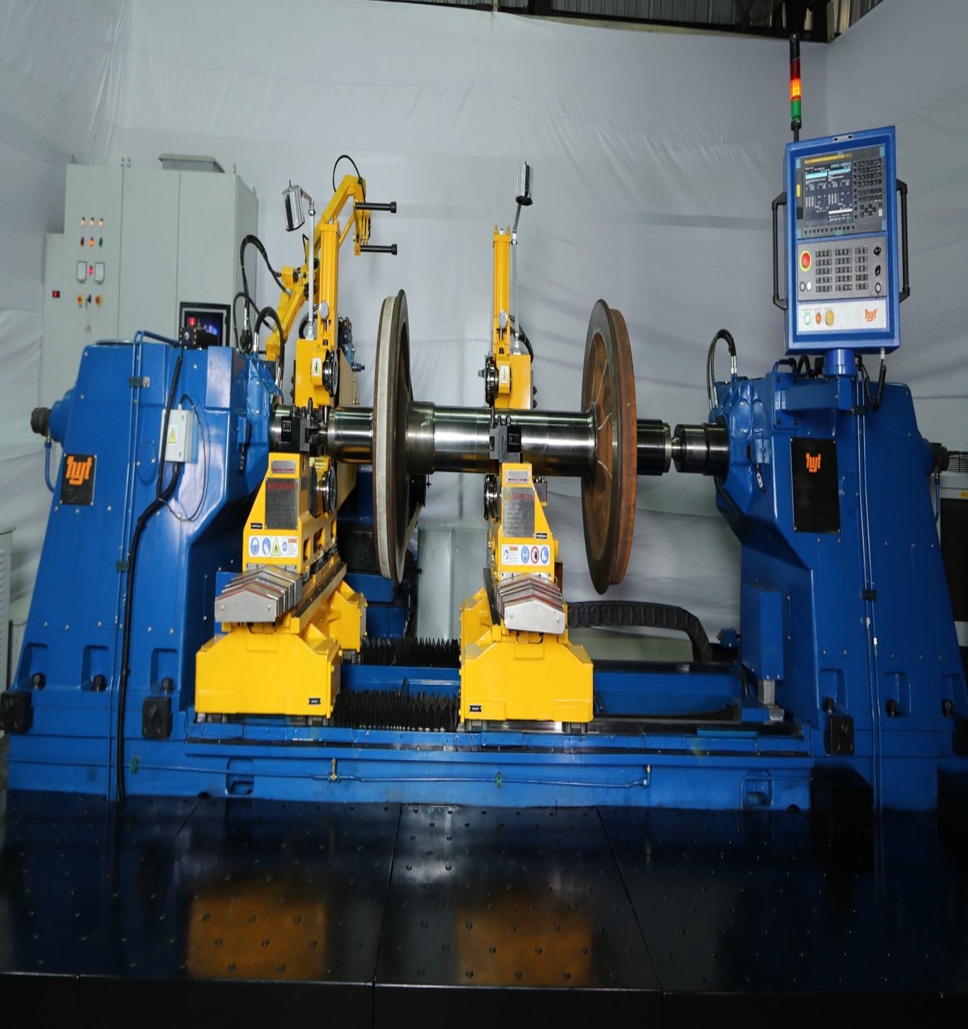
- CNC Surface Wheel Lathe
- CNC Underfloor Wheel Lathe
- CNC Tandem Underfloor Wheel Lathe
- CNC Portal Wheel Lathe
- CNC Vertical Turning & Boring Machine
- CNC Axle Journal Turning and Burnishing Lathe
- Multipurpose Armature machine
- Automated Train Washing Plant
- Rail cum Road Vehicle (Shunter)
- Exclusive Distribution for Products
CNC Surface Wheel Lathe
YSL-08
| Max. Main Drive Motor Capacity | 2 x 45 or 55 KW |
| Cutting Speed while Profiling | 25 to 80 m/min |
| Tool Post Feed for Wheel Profiling | 0.1 to 3.5 mm/rev |
| Tool Post Rapid Speed for Both Axes | 3000 mm/min |
| Max. Chip Cross Section while Profiling | 20 mm2 |
| Cycle Time / Wheel Set | 14-16 min. |
| Max. Tread Diameter | 1250mm* |
| Min. Tread Diameter | 750mm* |
| Wheel Width | 75 to 145mm |
| Max. Axle Length | 2750mm* |
| Min. Axle Length | 1200mm* |
| Max. Weight of Wheel Set | 50 kN |
| Max./Min. Dia. for Brake Disc Machining | 700/250mm |
*Depends on track gauge
| Wheel Profiling | |
| Max. Difference in Dia. of Both Wheels | <0.15mm |
| Accuracy of Wheel Profile when Compared with Standard Gauge | <0.2mm |
| Radial Run Out of Wheel | <0.2mm |
| Axial Run Out of Wheel | <0.2mm |
| Profile Surface Finish | <12.5µm Ra |
| Brake Disc Machining (Optional) | |
| Min. Surface Finish | <2.5µm Ra |
| Flatness of Surface | <0.1/100mm |
| Lateral Wobble | <0.2mm |
YSL-12
| Max. Main Drive Motor Capacity | 2 x 37.5 KW |
| Cutting Speed while Profiling | 25 to 80 m/min |
| Tool Post Feed for Wheel Profiling | 0.1 to 3.5 mm/rev |
| Tool Post Rapid Speed for Both Axes | 3000 mm/min |
| Max. Chip Cross Section while Profiling | 16 mm2 |
| Cycle Time / Wheel Set | 16-18 min. |
| Max. Tread Diameter | 1250mm* |
| Min. Tread Diameter | 750 mm* |
| Wheel Width | 75 to 145mm |
| Max. Axle Length | 2750mm* |
| Min. Axle Length | 1200mm* |
| Max. Weight of Wheel Set | 50 kN |
| Max./Min. Dia. for Brake Disc Machining | 700/250mm |
*Depends on track gauge
| Wheel Profiling | |
| Max. Difference in Dia. of Both Wheels | <0.3mm |
| Accuracy of Wheel Profile when Compared with Standard Gauge | <0.2mm |
| Radial Run Out of Wheel | <0.3mm |
| Axial Run Out of Wheel | <0.3mm |
| Profile Surface Finish | <12.5µm Ra |
| Brake Disc Machining (Optional) | |
| Min. Surface Finish | <2.5µm Ra |
| Flatness of Surface | <0.1/100mm |
| Lateral Wobble | <0.3mm |
YSL-21
| Max. Main Drive Motor Capacity | 1 x 22 KW |
| Cutting Speed while Profiling | 25 to 80 m/min |
| Tool Post Feed for Wheel Profiling | 0.1 to 3.5 mm/rev |
| Tool Post Rapid Speed for Both Axes | 3000 mm/min |
| Max. Chip Cross Section while Profiling | 10 mm2 |
| Cycle Time / Wheel Set | 50-60 min. |
| Max. Tread Diameter | 1250mm* |
| Min. Tread Diameter | 750mm* |
| Wheel Width | 75 to 145mm |
| Max. Axle Length | 2750mm* |
| Min. Axle Length | 1200mm* |
| Max. Weight of Wheel Set | 50 kN |
| Max./Min. Dia. for Brake Disc Machining | 700/250mm |
*Depends on track gauge
| Wheel Profiling | |
| Max. Difference in Dia. of Both Wheels | <0.5mm |
| Accuracy of Wheel Profile when Compared with Standard Gauge | <0.3mm |
| Radial Run Out of Wheel | <0.3mm |
| Axial Run Out of Wheel | <0.3mm |
| Profile Surface Finish | <12.5µm Ra |
Max./Min. Dia. for Brake Disc Machining on all products and all products pages.
CNC Surface Wheel Lathe is an automatic machine for simultaneous re-profiling new or worn-out wheels when disassembled from railway vehicles like locomotives, electrical and diesel multiple units, coaches, wagons, metro & tram coaches.
Pl. note that improvements is a continuous process. Hence, details explained above may undergo some changes meeting functional, quality and productivity requirements of the required technical specification.
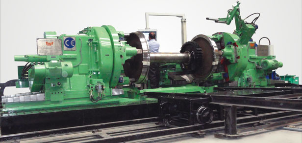
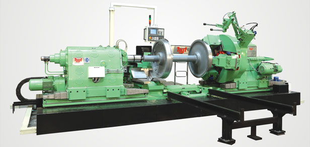
CNC Underfloor Wheel Lathe
YUL -08
| Max. Main Drive Motor Capacity | 4 x 15 KW |
| Cutting Speed while Profiling | 25 to 80 m/min |
| Tool Post Feed for Wheel Profiling | 0.1 to 2.5 mm/rev |
| Tool Post Rapid Speed for Both Axes | 3000 mm/min |
| Max. Chip Cross Section while Profiling | 10 mm2 |
| Max. Tread Diameter | 1500 mm* |
| Min. Tread Diameter | 540mm* |
| Wheel Width | 75 to 145mm |
| Max. Width of Vehicle (Rolling Stock) | 3600/3100 mm* |
| Min. Width of Vehicle (Rolling Stock) | 2900/2400 mm* |
| Max. Axle Length | 2750mm* |
| Min. Axle Length | 1200mm* |
| Max. Axle Load | 300/400 kN |
| Max./Min. Dia. for Brake Disc Machining | 700/250mm |
*Depends on track gauge
| Wheel Profiling | |
| Max. Difference in Dia. of Both Wheels | <0.1mm |
| Accuracy of Wheel Profile when Compared with Standard Gauge | <0.2mm |
| Radial Run Out of Wheel | <0.1mm |
| Axial Run Out of Wheel | <0.15mm |
| Profile Surface Finish | <12.5µm Ra |
| Brake Disc Machining (Optional) | |
| Min. Surface Finish | <2.5µm Ra |
| Flatness of Surface | <0.1/100mm |
| Lateral Wobble | <0.2mm |
Pl. note that improvements is a continuous process. Hence, details explained above may undergo some changes meeting functional, quality and productivity requirements of the required technical specification.
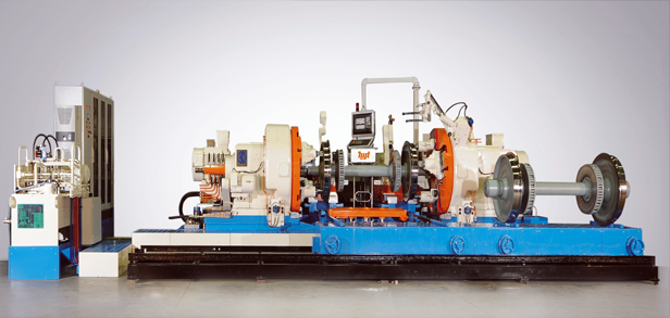
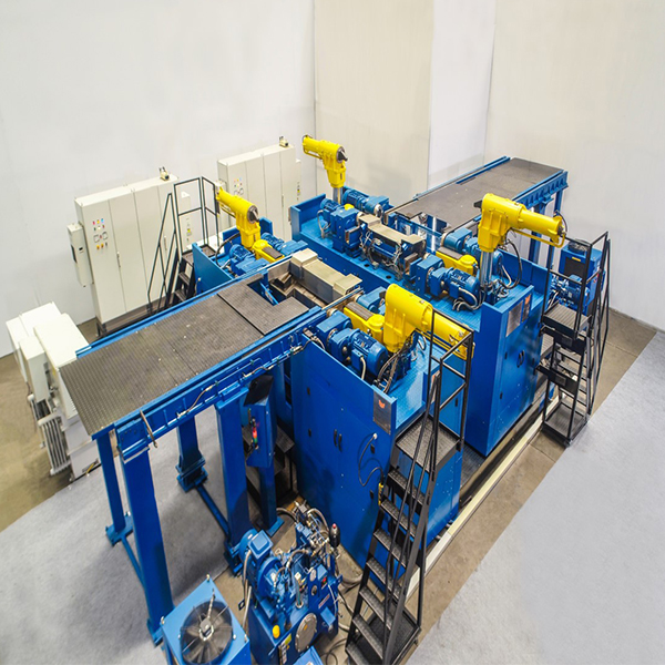
CNC Tandem Underfloor Wheel Lathe
A combination of two machines working in synchronised tandem mode
YUL -12T
| Max. Main Drive Motor Capacity | 4 Motors of 15 KW capacity each |
| Cutting Speed while Profiling | 20 to 120 m/min |
| Cutting Speed while Brake Disc Machining | 120 m/min (Constant) |
| Tool Post Feed for Wheel Profiling | 0.1 to 2.5 mm/rev |
| Tool Post Rapid Speed for Both Axes | 3000 mm/min |
| Max. Chip Cross Section while Profiling | 10 mm2 |
| Max. Tread Diameter | 1500mm* |
| Min. Tread Diameter | 540mm* |
| Wheel Width | 75 to 155mm |
| Max. Axle Load | 300/400 KN |
| Max. Width of Vehicle (Rolling Stock) | 3600/3100 mm* |
| Min. Width of Vehicle (Rolling Stock) | 2900/2400 mm* |
| Max. Axle Length | 2750mm* |
| Min. Axle Length | 1200mm* |
| Max./Min. Dia. for Brake Disc Machining | 700/250mm |
*Depends on track gauge
| Wheel Profiling | |
| Difference in Dia. of Both Wheels | <0.10mm |
| Accuracy of Wheel Profile when Compared with Standard Gauge | <0.2mm |
| Radial Run Out of Wheel | <0.10mm |
| Axial Run Out of Wheel | <0.15mm |
| Profile Surface Finish | <12.5µm Ra |
| Brake Disc Machining (Optional) | |
| Surface Finish | <2.5µm Ra |
| Flatness of Surface | <0.1/100mm |
| Lateral Wobble | <0.2mm |
- One of the machine is fixed and other machine is moveable to take care varying wheel base of bogie.
- Common rail system for both the machines. Individual Hydraulic & Pneumatic system for each machine.
- Each machine can work individually enabling profiling of individual wheel set also.
- Rigid basements in cast iron construction for supporting Mobile & Fixed machine.
- Linear motion guideways and pre-loaded ball screw for movement of mobile machine.
- Movement of moving machine by CNC system.
- All four drive rollers of both the machines moves up in synchronized mode with displacement feed back during lifting and centering of wheel set. All four drive rollers of both the machines in de-synchronized follow up mode during wheel profile turning to maintain positive contact with wheels having wear out defects.
- Provision to detect slippage between drive rollers and the wheel set.
- Each machine equipped with two CNC tool carriages for simultaneous measuring and machining of both wheels of wheel set
- Hardened & ground guideways with preloaded ball screws for very high and consistent accuracies.
- Equipped with quick change CAPTO/KM LOCK tooling for wheel profiling & brake disk machining.
- Each CNC Tool Carriage equipped with wheel profile and diameter measuring unit of proven design for Pre & Post measurement.
- Coach and locomotive re-profiling time is reduced by 50% and 33% respectively, resulting in higher availability of coach/locomotive for Revenue Service.
- Isolating a non-usable / sick coach and inserting a new coach is very time consuming and laborious activity. Hence, entire train can be brought on Tandem UFWL as the wheel profiling of coach will be completed within less than 2 hours.
Pl. note that improvements is a continuous process. Hence, details explained above may undergo some changes meeting functional, quality and productivity requirements of the required technical specification.
CNC Portal Wheel Lathe

YPL -02
| Max. Main Drive Motor Capacity | 2 x 55 KW |
| Cutting Speed while Profiling | 25 to 80 m/min |
| Tool Post Feed for Wheel Profiling | 0.1 to 4 mm/rev |
| Tool Post Rapid Speed for Both Axes | 4500 mm/min |
| Max. Chip Cross Section while Profiling | 32 – 50 mm2 |
| Cycle Time / wheelset | 8 – 12 mins |
| Max. Tread Diameter | 1250mm* |
| Min. Tread Diameter | 750mm* |
| Wheel Width | 75 to 145mm |
| Max. Axle Length | 2750mm* |
| Min. Axle Length | 1850mm* |
| Max. Weight of Wheelset | 50 KN |
| Max./Min. Dia. for Brake Disc Machining | 700/250mm |
*Depends on track gauge
| Wheel Profiling | |
| Max. Difference in Dia. of Both Wheels | <0.15mm |
| Accuracy of Wheel Profile when Compared with Standard Gauge | <0.2mm |
| Radial Run Out of Wheel | <0.1mm |
| Axial Run Out of Wheel | <0.2mm |
| Profile Surface Finish | <12.5µm Ra |
| Brake Disc Machining (Optional) | |
| Min. Surface Finish | <2.5µm Ra |
| Flatness of Surface | <0.1/100mm |
| Lateral Wobble | <0.2mm |
Pl. note that improvements is a continuous process. Hence, details explained above may undergo some changes meeting functional, quality and productivity requirements of the required technical specification.
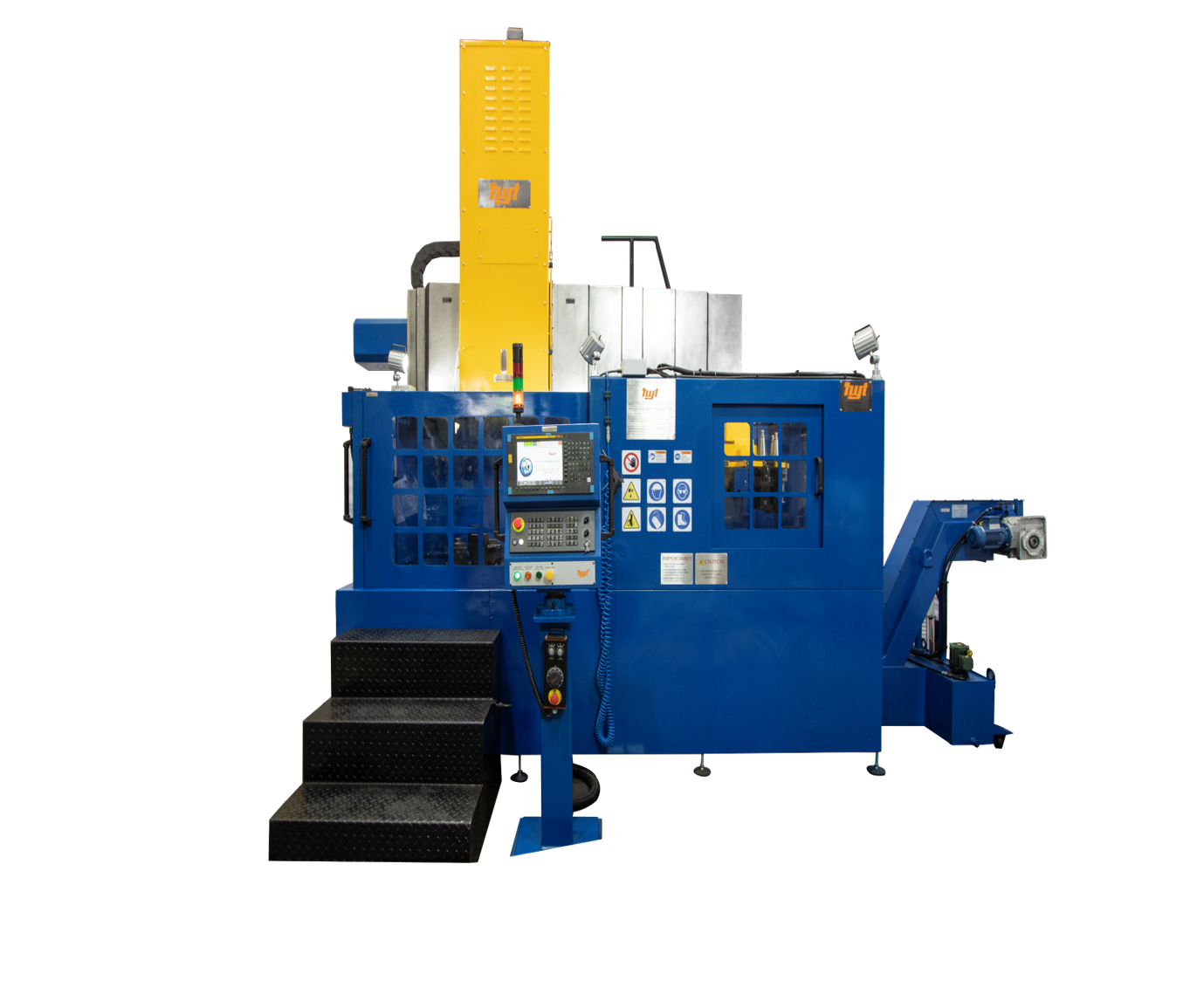
CNC Vertical Turning & Boring Machine
YVM -04
| Turning / swing diameter | 1600mm |
| Table diameter | 1400mm |
| Table speed | from 3 to300rpm |
| Turning height | 600mm |
| Vertical travel of the ram head | 700mm |
| Table Drive Motor Capacity | 45KW |
| Horizontal traverse of ram head | +900/-50 mm |
| Rapid traverse rate | 8000 mm/min |
| Ram cross section | 200 x 200 or 250 x 250 mm |
| Surface finish while boring | Ra 0.8 micron |
| Surface finish while turning | Ra 1.6 micron |
| Surface finish while facing | Ra 1.6 micron |
| Machine accuracies – As per ISO:3655 | |
| Vertical & horizontal travel of ram laser calibrated as per VDI DGQ 3441 | |
CNC Vertical Turning and Boring machine is suitable for Railway wheel front and back profile machining, hub boring and facing, rim front and back facing, tread and flange profile turning and various grooving operations. Various drilling and tapping operations as well as holes for brake disc mounting can be done on railway wheel by optional live spindle.
Pl. note that improvements is a continuous process. Hence, details explained above may undergo some changes meeting functional, quality and productivity requirements of the required technical specification.
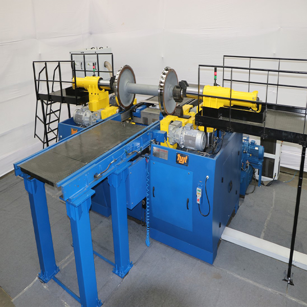
CNC Axle Journal Turning & Burnishing Lathe
YTB – 04
| Main Drive Motor Capacity | 11 KW |
| Cutting Speed for Axle Turning & Burnishing | 50 to 400 m/mins. |
| Tool Post Feed for Axle Turning & Burnishing | 0.1 to 2.5 mm/rev |
| Max. depth of cut while axle turning | 2 mm. |
| Max. Tread Diameter | 1250mm* |
| Min. Tread Diameter | 540mm* |
| Wheel Width | 75 to 145mm |
| Max. Axle Length | 2750mm* |
| Min. Axle Length | 1200mm* |
| Max. weight of wheel set | 50 kN |
| Min. – Max. Axle Journal diameter | 70-320 mm |
| Min. – Max. Axle Journal length | 110 – 480mm |
| Ovality of journal | <0.01mm |
| Taper of journal | <0.01/100mm |
| Surface finish of journal after burnishing | <0.2 µm Ra |
Pl. note that improvements is a continuous process. Hence, details explained above may undergo some changes meeting functional, quality and productivity requirements of the required technical specification.
Multipurpose Armature machine

YMM – 04
| Main Drive Motor Capacity | 15 KW |
| Carriage Rapid Traverse in Longitudinal Direction | 600 mm/min |
| Head Stock Spindle Speed – Infinitely Variable | 1.5 to 300 rpm |
| Carriage Feed in Longitudinal Direction | 0 to 100 mm/min |
| Maximum Depth of Cut while Commutator Turning | 2.5 mm |
| Maximum Banding Tension during Wire/Tape Banding | 300 Kg |
| Armature | |
| Maximum Armature Weight | 30 KN |
| Minimum Length Of Armature | 500 mm |
| Maximum Length of Armature | 1600 mm |
| Minimum Diameter of Armature | 500 mm |
| Maximum Diameter of Armature | 1400 mm |
| Commutator | |
| Minimum Diameter of Commutator to be Machined | 200 mm |
| Maximum Diameter of Commutator to be Machined | 900 mm |
| Minimum Length of Commutator to be Machined | 75 mm |
| Maximum Length of Commutator to be Machined | 450 mm |
| Accuracies | |
| Ovality of Commutator Turning | <0.015 mm* |
| Taper of Commutator Turning | <0.015 mm* |
| Uniformity of Banding Tension | <±10 Kg |
Pl. note that improvements is a continuous process. Hence, details explained above may undergo some changes meeting functional, quality and productivity requirements of the required technical specification.
Automated Train Washing Plant

| Train wash speed through plant | 3 to 5 KMPH |
| Fresh water requirement | Max. 60 litres per coach / car |
| Pressure of spray at nozzle outlet at final stage | Approx. 10Kg/sq.cm |
| Total width of the support structures stands along with cleaning implements etc. installed on the railway track | 5.5 meters (Max.) |
| Power Supply | 415V±10%, 50Hz±3% |
| Length of straight track between fouling marks | 50 Mtrs. (Max.) |
| Productivity | The end-to-end cycle time for cleaning a train for 24 coaches will not be more than 15 minutes. |
This coach washing plant is capable of automatic washing exterior lateral sides of the rail cars along with projected window bars, window sil areas.
The automatic washing cycle consists of :
- Pre-wetting / rinsing
- Spraying detergent
- Multiple Brushing stations
- Final rinsing
- Moping
Above mentioned cycle will be carried out when the train is moving at a speed of 3-5 kmph
Water conservation : water is recycled through effluent treatment plant
Optical laser sensors are installed for sensing the entry and speed of the railcars
Modular construction, Robust design, Low operation and maintenance cost
Pl. note that improvements is a continuous process. Hence, details explained above may undergo some changes meeting functional, quality and productivity requirements of the required technical specification.
Rail Based Loco Shunter

KRE 15 RCRV
| Type | Rail cum road vehicle |
| Service weight | 6 t +/- 10% |
| Max wheel load | Approx. 1.5T |
| Gauge | 1676 mm / 1435 mm |
| Max. Speed | V1 loaded 0 – 2 km/hr V2 solo 0 – 4 km/hr |
| Max. tract. effort | 15 kN at wheel rim at adhesion µ =0.5 in dry (0.3 in wet) |
| Towing capacity | 135T locomotive / other rolling stock at gradient from 0-2.5 per 1000. |
| Wheelbase | 1880 mm |
| Width | 2300 (2420) mm / 2060 (2180) mm |
| Height | max 1420 (1560mm including antenna) mm for visibility |
| Total length (without couplers) | 3080 mm |
| For Up railing | approx. 3.5m x 3.5m |
| Guiding wheels | 4 Nos. Steel flanged wheel, profile according to IR. CSL – 3040 or UIC 510, dia. 330mm |
| Traction / steering wheels | 4 Nos. Vulkolan / Polyurethane dia. 304 x 140 mm |
| Steering | 4-wheel: -crab side way, -perpendicular, -circular, -360 degrees rotating on own axis |
| Battery capacity | 80V, 460Ah waterless, with electrolyte mixing for less maintenance |
| Battery charger | Charging time max 10 hours, 415V, 3 Phase + earth, fused at 16A |
| E-system | 24 V PLC Iqan |
| Safety Integrity Level | SIL 3 |
OPTIONAL : Coupler as per requirement
Joint Manufacturing with BEMO Rail, Netherland. Pl. note that improvements is a continuous process. Hence, details explained above may undergo some changes meeting functional, quality and productivity requirements of the required technical specification.
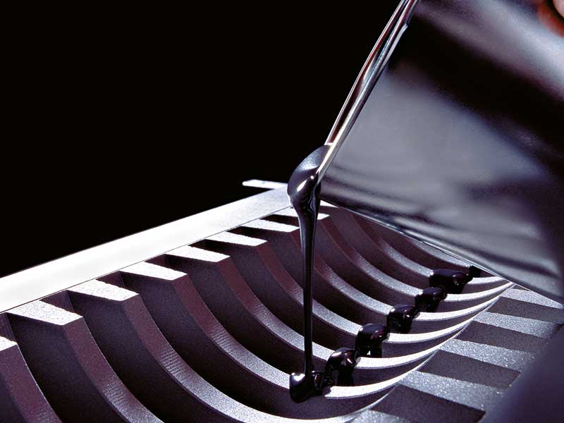
Exclusive distribution for products of SKC GLEITTECHNIK GMBH, Germany
SKC, a German technology company is the pioneer in the production and use of malleable viscous materials and a 35 year old company. High quality materials with quality management system according DIN EN ISO 9001.
Products : SKC compounds are two-component materials based on high quality epoxy resins. Various fillers and additives enable a tailor-made adaptation of the materials to the specific
- SLIDEWAY COATINGS (SKC 3, SKC 60, SKC 62, SKC 63, SKC 63 R, SKC 90, SKC 400 ELF)
- COATINGS WITH JOINT FACES (SKC 53, SKC 55, SKC 57, SKC 58)
- RELEASING COMPOUND (SKC 15 Releasing Compound, SKC 12 TRS Release Spray, SKC 14 Silicon Releasing Compound, SKC 14 TRS Release Spray, SKC 13 W Release Wax)
- ACCESSORIES